Author Archives: captainsailboat24

About captainsailboat24

I am a retired engineer who enjoys reading, boating, fiction writing, and spending time with family and friends. I've had a fascination with sailboats since I was a young man. My first experience with being on a sailboat was in the year 1996 off the Grand Cayman Island on a 37 foot sailboat, captained by a resident of Grand Cayman Island. We sailed out to Stingray island, spent an hour or so swimming with the stingrays, and sailed back. After I retired, I took up oil painting, then fiction writing, and now my wife and son are helping me restore a forty-year-old sailboat. We are learning a lot, and hopefully, we will be sailing this fall. That would be the fall of 2015. Update: Turned out to be the fall of 2016, who knew how long this would take? Obviously, I did not. The boat is now in the water.

Adding Covers To The Shroud Stays

The old gray covers on the four shroud stays were brittle, cracked, and coming apart. I read the purpose of the shroud covers are to protect the sails so they do not get discolored from rubbing up against the metal stays. I measured the size of the shroud stays and ordered four new covers. They fit perfectly. They are white.

image

Raising and lowering the Mast Part 1 of 2

The Mast is pretty heavy. We used muscle power to get it down when we purchased the boat. Later, we realized the boat rigging is designed so the mast can be raised or lowered using the existing rigging, once you remove the pin holding the backstay and reconnect it to the boom only.

The pin on the right that secures the backstay to the metal triangle plate has a button that has to be depressed to get the pin out. The pin cannot be removed without depressing that button.

My son studied the photos on the original sales brochure and figured out how to configure the rigging for raising and lowering the mast. One person can do it with the addition of three lines. Two lines hold the boom and keep it from falling off to the left or right. The third line is tied to the forward stay to break the mast loose from it’s upright position or the keep the mast from snapping into the place too harshly when raising. The photos did not depict the forward stay line. My son came up with that idea after he realized how easy that would be to do with one additional temporary line.

When the backstay line is released from the triangle plate and connected to boom only, the lines are used to lower or raise the mast. It is held into position by the wood cleat on the rear of the boat. The pulleys reduce the load enough that one person can easily raise and lower the mast by pulling or releasing the tension on the ropes. The photo on the right shows the position of the boom when the mast has been lowered.

It is a good system. We raised and lowered the mast several times to make sure we had the process down, before taking the boat to the launch site.

We have a video of the process. My son mounted a camera to the top of the mast while raising and lowering the mast. I will post a link to the video in an upcoming post.


Checking the sails and lines

All the existing lines needed to be replaced. Also we found one broken sail slug that needed replacing. I did a search online and found one seller who sold the kind of slug I needed for the 40 year-old boat. See package below for details.

We only needed one, but I ordered two to have a spare just in case we broke another one.

I ordered a hot knife to cut the lines and it worked well. I used painter’s tape before cutting. I let the weight of the hot knife rest on the line where I wanted to cut it. I pressed the trigger and when it started cutting I moved it back and forth slowly. I placed a wooden board under the line so as not to burn my cooler.

Replacing The Old Navigation Lights

The original navigation lights were foggy, melted, and corroded, so I searched online for exact replacements. I got pretty close to the original style.

IMG_0344IMG_0339

Above on the left is what the original stern and mast light style. On the right is the new

mast and stern lights we installed. The new lights came with incandescent bulbs, but we

used LED bulbs instead.

IMG_0664IMG_0658

Above photo is the red bow navigation light. There is also one with a green lens. These photos show the original bulb shipped with the new lights and the LED bulbs we used.

IMG_2959

Above are the original bow lights. Before are the new replacement lights.

IMG_2957

We replaced the old wiring with new marine wire. Below are photos

showing the marine wire we used for our navigation lights.IMG_4757

IMG_4758

Below are photos of the lights after we installed them on the boat.

IMG_5382.JPG

The Stern Light is above.

IMG_5386

The bow lights. LED bulbs have a polarity. Be sure to check the polarity before installing the cover. Although I checked for continuity, I failed to check the bulb polarity and had to remove both bow light covers and turn the bulbs around. They worked fine then.

mast-lights

While we were at it, we added LED lights at the top of the mast so we could light up the boat at night. We added a dimmer switch to adjust the brightness. If we are anchored on the water at night, we can illuminate the boat to whatever level of brightness we desire.

Outboard Motor Mount Installation

Time to measure and install: Approximately two hours.

Tools needed: electric drill, 12 inch long 3/8 inch drill bit, and two large clamps to hold the mount in position before drilling through the stern.

Installation Procedure:

Measure and drill holes in the wooden mount prior to drilling through the stern. I used the three pre-drilled holes in the wooden mount as my guide to drill holes in the 3/4 wooden backing plate I would be using inside the stern for additional support, instead of relying only on the fiberglass area immediately around the three bolt holes.

Before placing the mount on the stern, I cut a piece of rubber backing to go between the wooden mount and the fiberglass stern. I used painter’s blue tape to hold the rubber backing in place on the wooden mount.  I then used two adjustable wood clamps to hold the mount in place before drilling the first hole through the fiberglass stern. The first hole drilled was the lower bolt.

I installed the lower bolt through the mount and stern and placed a vise grip on the bolt head to prevent it from spinning. I crawled inside boat all the way back to the stern and placed the washers, lock nut, and nut onto the bolt. I tightened the nut enough to hold the mount secure, but loose enough to move the mount slightly to level it up before drilling the last two holes. As it turned out the mount did not move and it was still level, so I drilled the upper two holes, before repeating the process of installing the bolts, washers and nuts.

I installed the motor mount using 3/8 inch stainless steel nuts, bolts, and washers. I found out the best way to get the holes straight was to pre-drill the holes in the mount first and then back drill through the board that hold the motor. I first tried to drill larger holes in the larger board where the motor clampls, but one of the holes did not line up correctly. I will fill the larger holes and paint over them. I used a 3/4 inch wood backing plate inside the stern as additional support structure instead of relying on the fiberglass alone to carry the load. The board which was large enough to cover all three entry points spreads the load over a larger surface area instead of just around the three bolt holes.

The six horse power Nissan Outboard motor weights 60 pounds. The wooden mount easily supports four  times that weight.

Note: According to the installation manual, the water intake should be two inches below the bottom of the boat. I placed water intake five inches below the bottom of the sailboat, because the previous mount had not taken into consideration that the stern of the boat rises if a two hundred pound man stands on the bow of the boat, causing the stern to lift upward bringing the water intake above the water line.

Sailboat Outboard Motor mount 1 Sailboat Motor Mount 2

Motor mount backer  support 1

This 3/4 inch board located inside the boat behind the stern motor mount adds

strength by displacing the load across a larger area of the fiberglass instead of

just around the three bolts.

IMG_4779

Here is another photo taken from inside the boat. I had to crawl back to the stern area. It was fairly tight as you can see. You can see the electrical wires that go to the stern light. We will be replacing those old wires with new marine grade electrical wiring in an upcoming post.

Outboard Motor Mount Fabrication

Working time for this task was three hours for fabrication, thirty minutes for each coat of epoxy, primer, and final top coat of 100 acrylic paint.

Tools required, table saw, chop saw, belt sander, drill, 3/8 inch bit, and Phillips screwdriver bit. We used scrap treated lumber we had left over from other projects. We coated the wood with two part no-blush epoxy prior to priming and top coating.

The original motor mount  built into this boat when sold new was a swing down fiberglass unit held on by two hinges. See link below to get an idea of how the original motor mount worked. Scroll down to see a photo of the original motor mount design.

http://www.dolphin24.org/yankee24.html

Over time, the screw holes wore and the hinges became loose. When the previous owner purchased a new 6 horsepower outboard, he decided to remove the original mount and use a handmade wooden unit that could be secured to the stern with 3/9 inch bolts. Unfortunately, the previous owner discarded the original motor mount. I made a cardboard template to get the minimum dimensions and the angle correct.

When we purchased the boat, the existing motor mount was a handmade wooden mount that left the motor too high. When someone walked to the front of the boat the prop would come out of the water. We looked at several options, and decided to build a new wooden mount that was lighter, allowed the motor to sit low enough in the water and one that would last until we could get one fabricated out of aluminum.

Below is a photo of the motor mount that was being used when we purchased the boat.

outboard 2

Outboard 1

Below are photos of the new mount after cutting and assembly. We used screws and exterior wood glue to secure the parts together. The three inch deck screws can withstand a shear force load of 250 lbs each. The outboard motor weights 60 lbs.

IMG_4539 IMG_4540 IMG_4541

Next we applied a coat of epoxy to water proof the wood.

IMG_4551 IMG_4550 IMG_4549

After allowing the epoxy coat to dry. We will mount the unit with three four inch 3/8 inch stainless steel bolts. Two at the top and one in the lower center position.

IMG_4608

Next up we will drill new holes in the stern and mount the outboard motor. Should be fun.

Thank you for stopping by.

Happy Sailing.

Bottom Painting The Sailboat Part 2 of 2

Applying the latex primer coats and final top coat was easy. Time for each coat applied was about thirty minutes. The primer dried in two hours and was ready for the next coat in four, but we waited awhile because we wanted to decide on a color for the final top coat on the bottom. My son wanted yellow. I wanted a light blue color.

Below are photos taken after the first primer coat was applied.

IMG_4607 IMG_4606 IMG_4605 IMG_4604 IMG_4603 IMG_4602 IMG_4601 IMG_4600 IMG_4599

We also barrier coated and painted the rubber assembly, which can be removed from the topside. The photo below was taken last fall after we removed the bottom paint from it.

IMG_3070

Below is a photo of the rubber assembly after three barrier coats of two part epoxy and the latex primer coat had been applied.

IMG_4596

Bottom Painting the Sailboat Part 1 of 2

Time required for this task: Days and weeks of part-time work for us to clean and prepare the bottom of the boat. Had we been able to make it a concentrated effort, we could have done this in about twelve six hour work days.

So far, this has been the most difficult and time consuming task on the sailboat. Before you decide to tackle this job, research the Internet. There is a lot of information about removing old bottom paint. It is toxic, copper based, which is a heavy metal. You will need to wear protective clothing and eye protection.

We used two gallons of CM-15, a two-part epoxy, for the barrier coats. We could have used any number of barrier coat products, but CM-15 can be applied in hotter temperatures and is for hulls that can flex.

Before we could apply the barrier coat, we had to clean the hull and sand wet sand it with 80 grit sand paper. Below are photos of what the bottom looked like before we started cleaning.

We used a gasoline engine powered portable power washer to remove the old bottom paint. The boat had been in the water for seven years when we purchased it. Had we power washed it when it first came out of the water, all of the bottom paint would have easily been washed off. We waited two years to start cleaning and we had to power wash the bottom several times and use brushes and 80 grit sand paper to remove all of the bottom paint down to the old barrier coating.

DSCN3054 DSCN3057 DSCN3051 DSCN3039 DSCN3038

IMG_4342

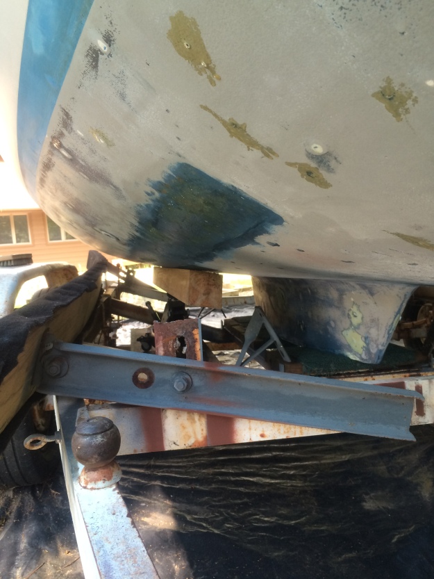
This photo shows how we painted underneath the bunks. We lowered the bunks and supported the boat with a 4X4 post on top of a hydraulic jack. This photo shows the difference between the old bottom paint and the old epoxy barrier coat ( Gray color ). We used two part epoxy to cover the places where we used a grinder to open the blisters. We used a straight edge to level it and then after it hardened we use an air sander to smooth them out.

Below are photos that show what the bottom looked like after power washing and sanding.

clean hull clean hull 2

Once the oil paint was removed we found more blisters and had to repair them. We used an air-powered sander to remove the raised part of the blisters and cut back until we had solid fiberglass or gellcoat. Only one blister used a liquid while we were grinding out the blisters.

When that happens, you should allow that blister to dry completely before going to the next step. Drying may require days. Below is a photo of blisters we found around the stub keel. The photo shows what they looked like after we used the small air-powered sander to remove the loose fiberglass. The blisters in the photo were ready for the next step. We mixed some two part no-blush epoxy and applied it to the areas shown making sure to extend outward around the blistered areas so they were completely covered. We did this to all of the blisters on the bottom and waited 24  hours for the epoxy to harden.

IMG_4396

The photos below show the bottom after the first new coat of barrier paint had been applied. The next day, we realized we had a major problem. It was not dry and sticky to the touch. It should have been dry to the touch in five hours. We contacted the manufacturer and he said we did not mix it correctly. We told him we followed the instructions on the can. He quit responding after my son sent him a photo of the instructions on the can.

IMG_4504 IMG_4505 IMG_4506 IMG_4507 IMG_4508

Notice the area under the bunks. We had to figure out how to get to that area so we could paint it. We found that the stub keel was strong enough to support the boat. so we removed one bunk at a time, after we strapped both sides of the boat and added boards under the rub rail to keep it from rolling over. That worked and the boat was steady and never moved.

Four days, later, the first barrier coat was still not completely dry on about 40 percent of the bottom. We posted our dilemma on Sailboatowners ( dot ) com and got some suggestions. We tried removing the tacky epoxy with de-natured alcohol, Ascentone, and a paint scraper so we could start over. This did not work. All we got off was a black stain. The epoxy would not come off. One person suggested we try a second coat and see if the hardening process would restart.

We did a test coat and the next day, that section was dry. Either one of two things happened. The hardening process restarted and the two coats chemically bonded or the second coat encapsulated the first coat and stuck to to it. We mixed a new batch of CM-15 and applied it to the boat. It was dry to the touch in five hours.

Below are the photos of the test area to see if the second coat idea would work.

IMG_4536 IMG_4537

Once we realized that worked, we mixed a new batch of CM-15 and applied it to the whole bottom.

Ivory Barrier coat 1 (2) Ivory Barrier coat 1 (3)

Below is a photo of the third and final barrier coat we applied. Notice both bunks were removed to allow access beneath the bunk area for painting. We used two straps on each side and 2 x 8 boards secured beneath the rub rails to keep the boat from rolling over. The boat never moved, since the stub keel is twelve inches wide and capable of supporting the entire weight of the boat.

Ivory Barrier coat 1 (1)

Next up is Bottom Painting the Sailboat Part 2 of 2 where we applied the latex primer coat before applying the final 100 percent acrylic top coat.

Thank you for stopping by our blog. Happy sailing.


All Eight Windows Re-installed On The Sailboat

Time requirement for this task: 3 hours.

This is a two person job. One person on the outside pressing and holding the window in place while the person inside the boat inserts the other half of the aluminum frame and tightens the screws that pull the two halves of the aluminum frames together.

My son and I re-installed all eight windows in our Seahorse 24 sailboat. We used Butyl tape to seal the windows. We got some great advice from a member of the Sailboatowners (dot) com forum. Use Butyl tape instead of silicone. Turned out to be great advice. We purchased the Butyl tape from Amazon Dicor (BT-1834-1 ) 1/8′ x 3/4 inch x 40 feet. One roll was more than enough to seal around all eight windows. We started out trying to roll the tape into a long pencil sized rope to place around the window before placing into the port holes. This did not work and wasted a lot of tape.

What did work well was to lay the tape flat around the perimeter of the window openings before placing the aluminum window frame into place. We pulled the windows down tight from inside with the screws that compressed the two halves of the aluminum frames together and this pushed out any butyl tape that was not necessary. Had we done this to start with we would have used much less tape and saved ourselves an hour of time.

We can now see through the windows.

Below are photos taken after we removed all eight windows, cleaned and repainted the topside. Further down are photos of the windows after we reinstalled them.

IMG_4229 IMG_4230 IMG_4231 IMG_4232 IMG_4233 IMG_4234 IMG_4235 IMG_4236 IMG_4238 IMG_4239

Next up on our list of tasks: Bottom painting the boat.